MED-EL
Published Mar 12, 2024
New in MAESTRO 10: Impedance Field Telemetry Heat Maps
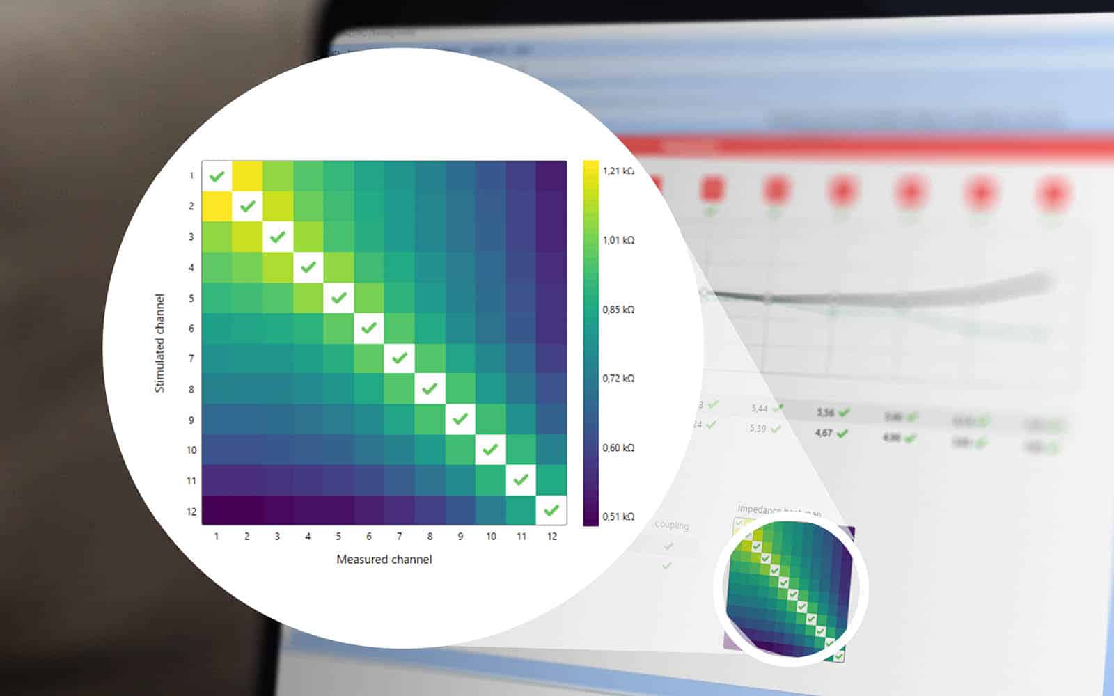
The latest MAESTRO cochlear implant fitting software comes with some practical new features, including color-coded IFT heat maps. IFT results are measured in seconds, and you can see the impedance status intuitively at a single glance.

Impedance field telemetry provides reliable pre-, intra-, and postoperative information about technical defects as well as possible incorrect positioning of electrode arrays in the cochlea. It can be used for anything from routine implant short circuit checks to checking the position of the electrode array.
What Results Can Impedance Field Telemetry Measurements Provide?
Impedance matrix measurements make it possible to find out the impedance status in seconds. Even when the implant is still in the packaging, IFT can be used to find out whether the flow of current is being compromised by a short circuit.
Possible error diagnoses:
- The measured voltage and resistance of the electrode channel are too high and there is not an effective flow of current (“HI channel”). This can be caused by damage to wires in the electrode array.
- The measured voltage of the electrode channel is lower than expected.
- The stimulation channel is technically working, but there is a short circuit between two channels.
How to Use the Results
An intraoperative position check performed shortly before closing up the wound can provide you with reliable and clear signs of incorrect electrode positioning. Franke-Trieger finds that compared to SoE measurements (Spread of Excitation), the voltage matrix “is the preferred method for clinical intraoperative position checks” due to its efficiency and “short measurement time of less than 10 seconds.”Franke-Trieger et al. (2022): Intraoperative Lagekontrolle von MEDEL Elektroden mittels Spread of excitation und Spannungsmatrix, Posterpräsentation, 24. Jahrestagung der Deutschen Gesellschaft für Audiologie, Erfurt, September 2022.[1]
It is very important to detect incorrect positioning early because not doing so can reduce the stimulation range, make fitting more difficult, and compromise hearing outcomes considerably.Gabrielpillai, J., Burck, I., Baumann, U., Stoever, T., Helbig, S. (2018) Incidence for Tip Foldover During Cochlear Implantation. Otology Neurotology 39 (9): 1115–1121.[2]McJunkin, J.,L., Durakovic, N., Herzog, J., & Buchman, C.,A. (2018) Early Outcomes With a Slim, Modiolar Cochlear Implant Electrode Array. Otology Neurotology 39 (1): e28-e33.[3]Lang, C.P., Salcher, R., Timm, M., Teschner, M,. Lenarz, T. (2018) Tip Fold-over with the Slim Modiolar electrode (CI 532), a retrospective case series. Laryngo-Rhino-Otologie 97 (S 02): 211.[4]Dhanasingh/Jolly (2018): Review on cochlear implant electrode array tip fold-over and scalar deviation.[5]Hans et al. (2021): Transimpedance Matrix Measurements Reliably Detect Electrode Tip Fold-over in Cochlear Implantation. Otology & Neurotology 42 (10): e1494–e1502.[6]Vanpouke et al. (2012): Assessing the Placement of a Cochlear Electrode Array by Multidimensional Scaling. IEEE Transactions on Biomedical Engineering 59 (2): 307-310.[7]
With the help of IFT heat maps, you can identify extracochlear electrode contacts easily. De Rijk et al. (2020): Detection of Extracochlear Electrodes in Cochlear Implants with Electric Field Imaging/Transimpedance Measurements: A Human Cadaver Study. Ear and Hearing 41 (5): 1196.[8]Von Mitzlaff et al. (2020): Electrode migration after cochlear implantation. Cochlear Implants International.[9] And interoperative measurements provide you with the information you need to make position corrections during surgery.
You should deactivate postoperatively detected extracochlear electrode contacts so your patients can achieve the best possible outcomes.
If you perform IFT, a postoperative CT-scan to check the electrode positions is generally not necessary—but a post-op CT or X-ray is needed to detect exact tonotopic electrode contact positions for anatomy-based fitting. (Recent studies suggest, however, that identification of electrode contact position may be possible with IFT. Aebischer et al. (2021): Intraoperative Impedance-Based Estimation of Cochlear Implant Electrode Array Insertion Depth. IEEE Transactions on Biomedical Engineering 68 (2): 545-555.[10]Schraivogel et al. (2023): Postoperative Impedance-Based Estimation of Cochlear Implant Electrode Insertion Depth. Ear and Hearing 44 (6): 1379-1388.[11])
From a postoperative perspective, IFT via MAX coil or audio processor coil done simply and quickly at any fitting appointment also serves as a way to regularly check the functioning of implanted components and find out the compliance limit which affects the charging settings.
Established Process, New Visualization
IFT is a method that has been tried and tested for decades. And as a pioneer in this field, MED-EL has built on decades of experience. In the latest version of MAESTRO, IFT results are displayed after just a few seconds as a user-friendly, color-coded heat map.
Since the measurement method hasn’t changed, all earlier measurements are also shown in the same new color scheme. Additionally, you can display the most recent impedance matrix next to any previous matrix of any MED-EL cochlear implant to compare them.
The intuitive graphics replace the number matrix that had previously made it necessary to calculate certain incorrect positions, such as an extracochlear position or buckling.
Speed is an additional advantage of the new IFT measurements. Measurements in MAESTRO 10 are performed much faster than in competitors’ systems—they only take about 10 seconds.
Examples of the New Intuitive Impedance Field Telemetry Heat Maps
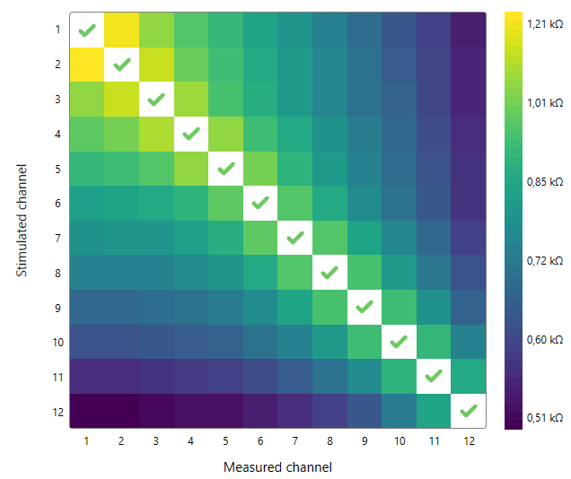
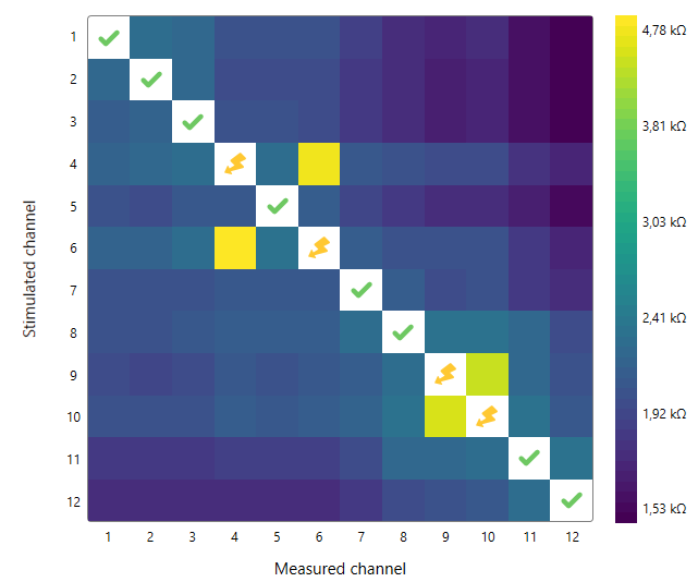
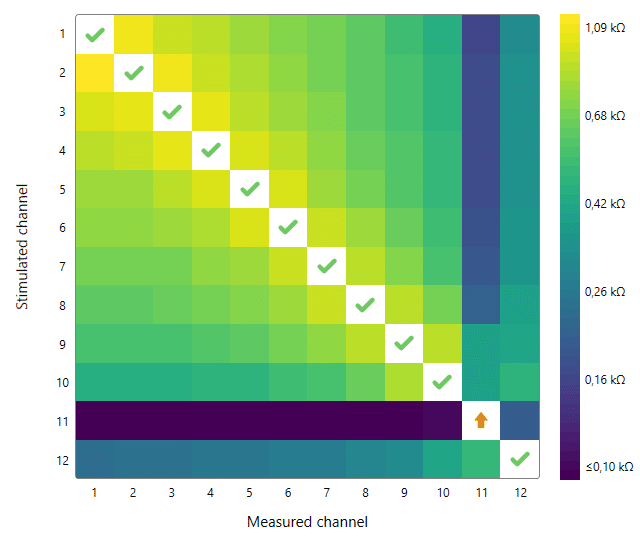
Time for a few illustrations from the new MAESTRO software! They’ll show you how intuitive and self-explanatory it is to check the impedance status. The color coding shows the voltage difference between the measured contact and reference contact. Lighter colors indicate a higher voltage, and darker colors indicate a lower voltage. If there is a short circuit, other contacts are activated along with it as a consequence.
A consistent transition from lighter to darker colors with increased distance from the stimulated electrodes shows the desired electrode status:

This is what it looks like if there are multiple short circuits. The graphic shows that channels 4, 6, 9, and 10 are not working properly:

The following illustration shows that channel 11 is a HI channel. The other channels are working normally:

Further Reading
Learn more about other factors—in addition to an optimally fitted and positioned electrode—that contribute to increased hearing success and the closest to natural hearing with a cochlear implant.
Subscribe to the MED-EL Professionals Blog
Regularly receive articles, case studies, and information about new product features directly to your inbox.
SubscribeReferences
-
[1]
Franke-Trieger et al. (2022): Intraoperative Lagekontrolle von MEDEL Elektroden mittels Spread of excitation und Spannungsmatrix, Posterpräsentation, 24. Jahrestagung der Deutschen Gesellschaft für Audiologie, Erfurt, September 2022.
-
[2]
Gabrielpillai, J., Burck, I., Baumann, U., Stoever, T., Helbig, S. (2018) Incidence for Tip Foldover During Cochlear Implantation. Otology Neurotology 39 (9): 1115–1121.
-
[3]
McJunkin, J.,L., Durakovic, N., Herzog, J., & Buchman, C.,A. (2018) Early Outcomes With a Slim, Modiolar Cochlear Implant Electrode Array. Otology Neurotology 39 (1): e28-e33.
-
[4]
Lang, C.P., Salcher, R., Timm, M., Teschner, M,. Lenarz, T. (2018) Tip Fold-over with the Slim Modiolar electrode (CI 532), a retrospective case series. Laryngo-Rhino-Otologie 97 (S 02): 211.
-
[5]
Dhanasingh/Jolly (2018): Review on cochlear implant electrode array tip fold-over and scalar deviation.
-
[6]
Hans et al. (2021): Transimpedance Matrix Measurements Reliably Detect Electrode Tip Fold-over in Cochlear Implantation. Otology & Neurotology 42 (10): e1494–e1502.
-
[7]
Vanpouke et al. (2012): Assessing the Placement of a Cochlear Electrode Array by Multidimensional Scaling. IEEE Transactions on Biomedical Engineering 59 (2): 307-310.
-
[8]
De Rijk et al. (2020): Detection of Extracochlear Electrodes in Cochlear Implants with Electric Field Imaging/Transimpedance Measurements: A Human Cadaver Study. Ear and Hearing 41 (5): 1196.
-
[9]
Von Mitzlaff et al. (2020): Electrode migration after cochlear implantation. Cochlear Implants International.
-
[10]
Aebischer et al. (2021): Intraoperative Impedance-Based Estimation of Cochlear Implant Electrode Array Insertion Depth. IEEE Transactions on Biomedical Engineering 68 (2): 545-555.
-
[11]
Schraivogel et al. (2023): Postoperative Impedance-Based Estimation of Cochlear Implant Electrode Insertion Depth. Ear and Hearing 44 (6): 1379-1388.
References

MED-EL
Was this article helpful?
Thanks for your feedback.
Sign up for newsletter below for more.
Thanks for your feedback.
Please leave your message below.
CTA Form Success Message
Send us a message
Field is required
John Doe
Field is required
name@mail.com
Field is required
What do you think?
The content on this website is for general informational purposes only and should not be taken as medical advice. Please contact your doctor or hearing specialist to learn what type of hearing solution is suitable for your specific needs. Not all products, features, or indications shown are approved in all countries.

MED-EL

MED-EL


